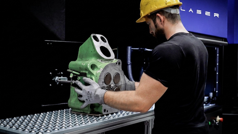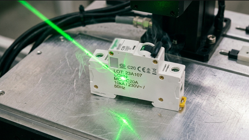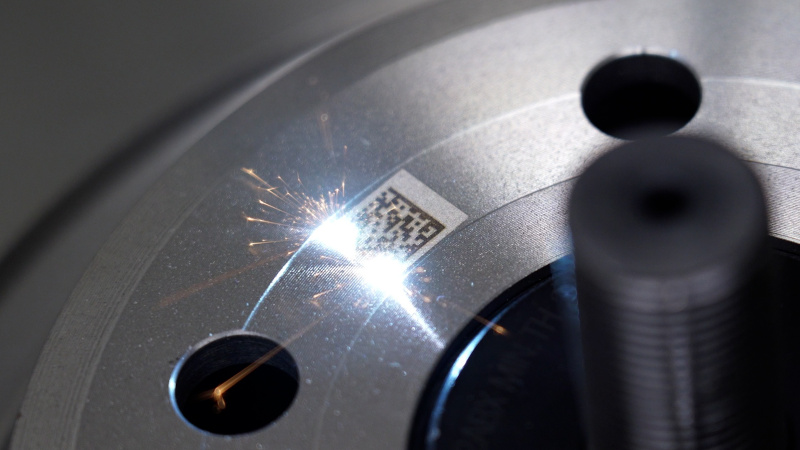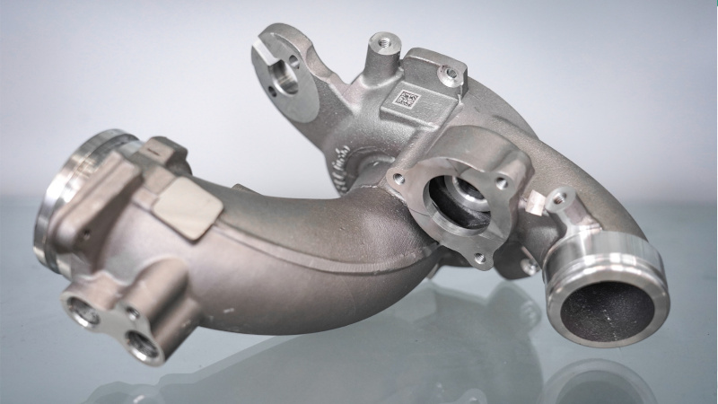
The topic of traceability is becoming increasingly important across many critical industries and supply chains, particularly for companies that need to outsource part of their production processes to third parties.
For these companies, it is therefore essential to monitor their products and ensure complete traceability throughout every stage of the production process.
Laser marking systems deliver excellent results in this area, creating permanent codes and markings quickly and cost-effectively. This is why laser technology is now one of the most widely used solutions for industrial traceability.
Marking, however, is not the end goal but the starting point of a chain. The marked code identifies the component, reading it turns the physical mark into data, and that data is linked to production information and subsequent events throughout the product lifecycle. This history is what makes traceability possible.
If the mark is not readable, or deteriorates prematurely, the link between the object and its information is broken.
What Is Traceability?
Traceability is an identification system that brings together a set of information and can track:
- history,
- location,
- origin,
- batch number,
- time,
- date,
- the movement of the product or a component through recorded information.
Traceability makes it possible to answer simple questions such as: who manufactured the product? When was it manufactured? And where was it manufactured?
Traceability is a requirement imposed by national or international regulations in many industrial sectors and for specific types of products.
Due to strict government regulations concerning the safety of food, medicines, defence, automotive products and minerals, product monitoring and traceability have become an integral part of manufacturing processes.
The concept of traceability applies both to the manufacturing industry, which produces products such as automobiles, and to process manufacturing, which includes products such as chemicals.
Traceability makes it possible to track movements one step backwards and one step forwards at any point in the supply chain and production processes, and therefore represents a form of insurance and a guarantee of product quality.

Product, Batch and Individual Component: Identification Levels
The level of traceability depends on what is chosen to be identified, and this choice affects both the content of the code and how the data is managed.
Three levels can be distinguished:
- Product: the code identifies the type of item (item code, part number or, in the GS1 system, GTIN). All units of the same model carry the same identifier: it tells you what the object is, but not which production run it comes from.
- Batch: the product code is supplemented by a batch number, which groups items manufactured under homogeneous conditions (same shift, same casting, same raw material batch or same machine configuration, according to the rules defined by the company). This makes it possible to narrow down a problem to a specific group of items.
- Individual component (serialisation): each item is assigned a serial number. Two components from the same batch remain distinguishable, and each can be linked to its own history.
The three levels are not mutually exclusive: the same code can contain the product identifier, batch number and serial number.
Laser marking is particularly well suited to more granular identification levels, because the code content can be generated by software for each individual item, without changing tooling, unlike systems based on fixed stamps or dies.
Serial Numbers, Scrap, Non-Conformities and Recalls
A serial number becomes valuable when it is associated in the database with the component’s production data: processing date and time, production line and machine, shift, batches of raw materials and semi-finished products used, process parameters and inspection results.
By reading the code, it is therefore possible to trace the production history of an individual component (the backward traceability mentioned above) or, starting from a material batch or a production day, identify all the items derived from it and their destination (the forward traceability process).
It is this two-way traceability that makes traceability a valuable quality tool. When a non-conformity is identified, the data linked to the codes makes it possible to define the scope of the problem: which batches or serial numbers were produced under the affected conditions, which items are still at the plant and which have already been shipped. Instead of treating the entire production run as potentially affected, scrap, rework and inspections can be focused on the items actually involved.
The same mechanism supports the management of recalls and field interventions, with effectiveness increasing as identification becomes more granular: with only a product code, a recall tends to involve the entire model; with a batch number, it can be narrowed down to a specific group of items; with a serial number, it can reach, where distribution data has been recorded, the individual components concerned.
Laser Marking for Traceability
Today, companies are looking for the most effective solutions to ensure the traceability of their products, which is why they are increasingly turning to laser applications. Traceability is a key factor that can help improve brand positioning and the perception of its quality among end consumers.
To trace a product or component, it must first be marked with an identification code. This makes each item uniquely identifiable and makes it easier to manage potential malfunctions or trace the supplier of a defective batch.
Traceability begins when laser equipment is used to mark parts directly with unique identifiers or other information (for example, the European product identifier EAN Code – European Article Number). The factory collects and stores this information in a secure database, allowing the parts to be monitored throughout the entire production process. From point A to point Z, intelligent software records the complete history of the component.
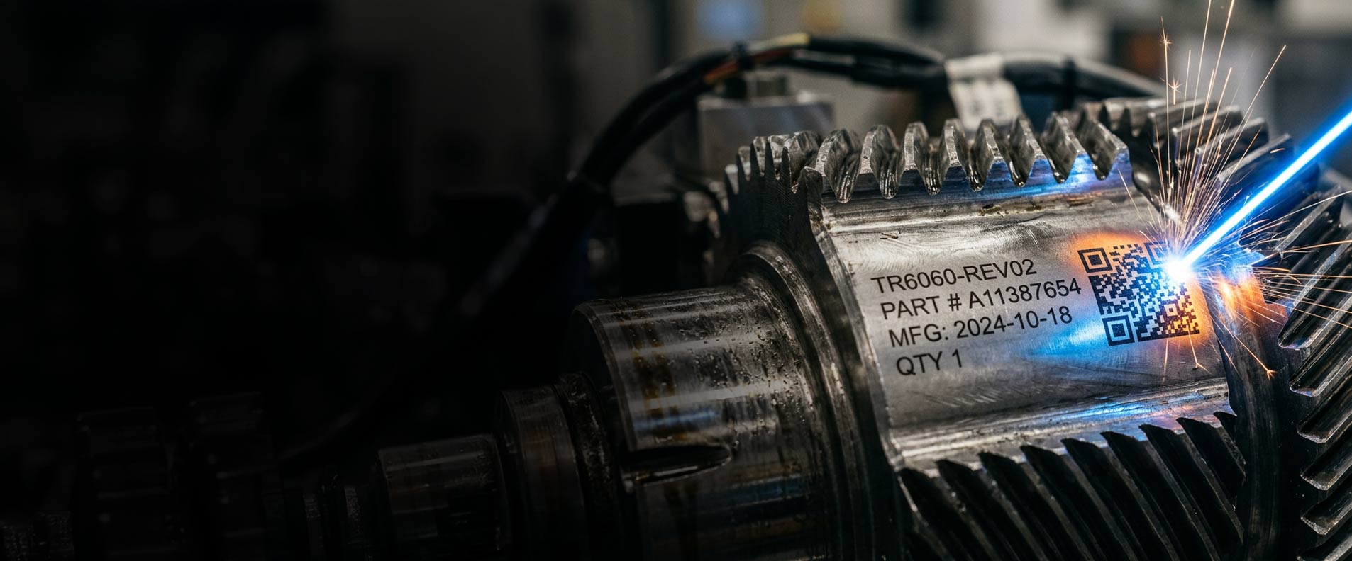
When the code is created directly on the surface of the component, without applying labels or tags, this is known as Direct Part Marking (DPM).
Unlike a label, direct marking cannot peel off or be replaced and remains permanently attached to the component, provided that it is designed to withstand the processes and environments to which it will be exposed: subsequent machining, heat treatments, painting, washing and sterilisation.
Laser marking is one of the most widely used DPM technologies, alongside other techniques such as dot peen marking, each with its own specific applications.
The Component Lifecycle: An Identity from Production to Replacement
The history of a component is built step by step, with the marked code providing access to the relevant information at each stage.
A typical process can be described as follows:
- Production: the code is marked, often during the early stages of the production cycle, and associated in the management system or MES with processing data and the batches of materials used. Marking early makes it possible to record subsequent operations from the outset, but requires the code to withstand those operations.
- Inspection: test results, measurements and inspections are recorded against the serial number or batch, allowing each item to carry its own compliance status.
- Assembly: by reading the codes of the components being assembled, the actual bill of materials of the finished product can be created, establishing the link between the assembled unit and the serial numbers of its subcomponents.
- Logistics: the code links individual items and assemblies to shipments, customers and destinations.
- Installation: the component is linked to the machine, vehicle or system in which it is installed.
- Maintenance and replacement: during servicing, reading the code makes it possible to identify the component, verify its origin, record maintenance activities and link any replacement part to the equipment’s service history.
For this continuity to work, the marking must remain readable for as long as the component may need to be identified, which in some industries means throughout the entire lifetime of the product.

Code Types: Barcodes, QR Codes and DataMatrix
Barcodes, or one-dimensional barcodes, are the most traditional example of alphanumeric codes that have been used for decades because they are simple and easy to read.
In the 1990s, two-dimensional codes were introduced to meet the needs of large-scale industrial production, where significantly more information needs to be associated with products and components.
There are many types of two-dimensional or 2D codes that can be laser marked. Among them, QR Codes and DataMatrix codes are particularly widespread. The latter is used especially in the automotive and medical sectors because it can encode a large amount of information in a small space and remain readable even when partially damaged.
For further information, read -> DataMatrix and 2D Codes: Laser Marking for Traceability and Quality
Another type of code that can be applied using laser technology is the unique UDI alphanumeric identification code, which stands for Unique Device Identification. This system is designed to provide globally unique and harmonised identification of medical devices for distribution and use, requiring the device label to carry a unique device identifier.
In the European Union, UDI is governed by Regulation (EU) 2017/745 (MDR) and consists of two parts that reflect the identification levels described above: the UDI-DI identifies the device manufacturer and model, while the UDI-PI identifies the production unit through data such as the batch number, serial number or dates. The UDI-PI is what links the individual device to its production history; one of the formats in which UDI can be represented is the GS1 DataMatrix, described below.
For reusable devices that are cleaned, disinfected or sterilised between uses, the MDR requires the code to be applied directly to the device and remain readable after each reprocessing cycle: a typical case in which direct marking maintains the link between the instrument and its data throughout its entire useful life.
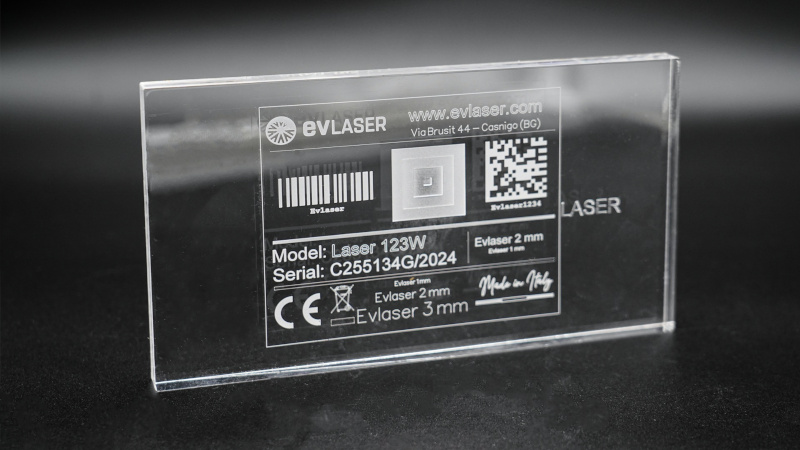
For further information, read -> Laser Marking of Plates and Labels for Codes, Text and Logos

GS1 DataMatrix: Product, Batch, Serial Number and Dates in a Shared Syntax
DataMatrix defines how data is represented graphically, but not what that data means. To trace a component through a supply chain involving multiple companies, a common syntax is also required, allowing the reading system to distinguish a batch number from a date or serial number.
This is the role of GS1 DataMatrix, which encodes data according to the rules of the GS1 system (identified to the reader by a dedicated initial character, FNC1).
Each piece of information is preceded by a GS1 Application Identifier (AI), a numerical prefix that defines its meaning and format. Some of the most common AIs used for traceability include:
- (01) GTIN: the global product identifier, consisting of 14 digits;
- (10) batch number and (21) serial number: alphanumeric, up to 20 characters;
- (11) production date and (17) expiration date: in YYMMDD format.
In the human-readable version, the AIs are shown in parentheses, for example (01)09501101020917(17)190508(10)ABCD1234(21)10; the parentheses are not encoded in the symbol.
For traceability, the advantage is twofold: a single scan provides the three levels of identification (product, batch, item) together with the relevant dates, already structured, and any system compliant with GS1 standards interprets them in the same way.
However, each additional AI increases the number of characters to be encoded and therefore, as we will see below, the size of the code. Choosing which data to include is therefore a design decision that must be evaluated in relation to industry requirements and the space available on the component.
Code Size and Readability: How Small Can a Code Be?
One of the most common questions in traceability projects concerns the space available on the component. The answer depends on a chain of relationships: amount of data → number of modules → code size → individual module size, together with the marking process, the material and the system that will be used to read the code.

Amount of Data, Number of Modules and Code Size
A 2D code such as DataMatrix consists of a matrix of modules, or cells. Their number cannot be chosen freely: it depends on the amount and type of data to be encoded and on the space allocated for error correction.
The more characters are included, the more modules are required: in DataMatrix ECC200, square matrices range from 10×10 to 144×144 modules, with some rectangular versions available for elongated spaces. Numeric-only sequences can be encoded more compactly than alphanumeric ones.
The physical size of the code is determined by the number of modules per side multiplied by the size of each individual module, plus the quiet zone around the symbol. This leads to two practical consequences:
- with the module size kept constant, adding data (a longer serial number, an additional date) increases the size of the matrix and therefore the overall footprint of the code;
- with the available space on the component kept constant, more data means smaller modules.
A purely mathematical example: a matrix of 16×16 modules with a module size of 0.25 mm occupies 4×4 mm; if adding data increases the matrix to 24×24 modules, with the same module size the code occupies 6×6 mm, excluding the quiet zone.
The first way to keep the footprint small is therefore to encode only what is necessary: in many cases, a unique identifier is sufficient, leaving the database to store the other information associated with the component.
Laser Spot, Optics, Process and Material
Once the number of modules has been defined, it is necessary to determine how small each individual module can be. There is no single limiting factor: the result depends on the combination of optics, parameters, material and process.
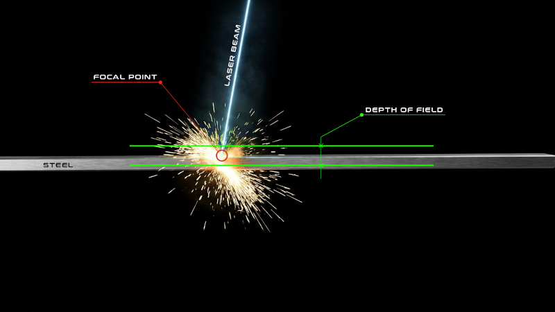
- Spot size and focusing optics: the diameter of the focused beam, which depends on the source, lens and marking field, places a limit on the achievable detail. However, a module is filled using multiple scan lines or pulses, and the actual size of the mark also depends on how the beam interacts with the material: spot size alone does not determine the minimum module size.
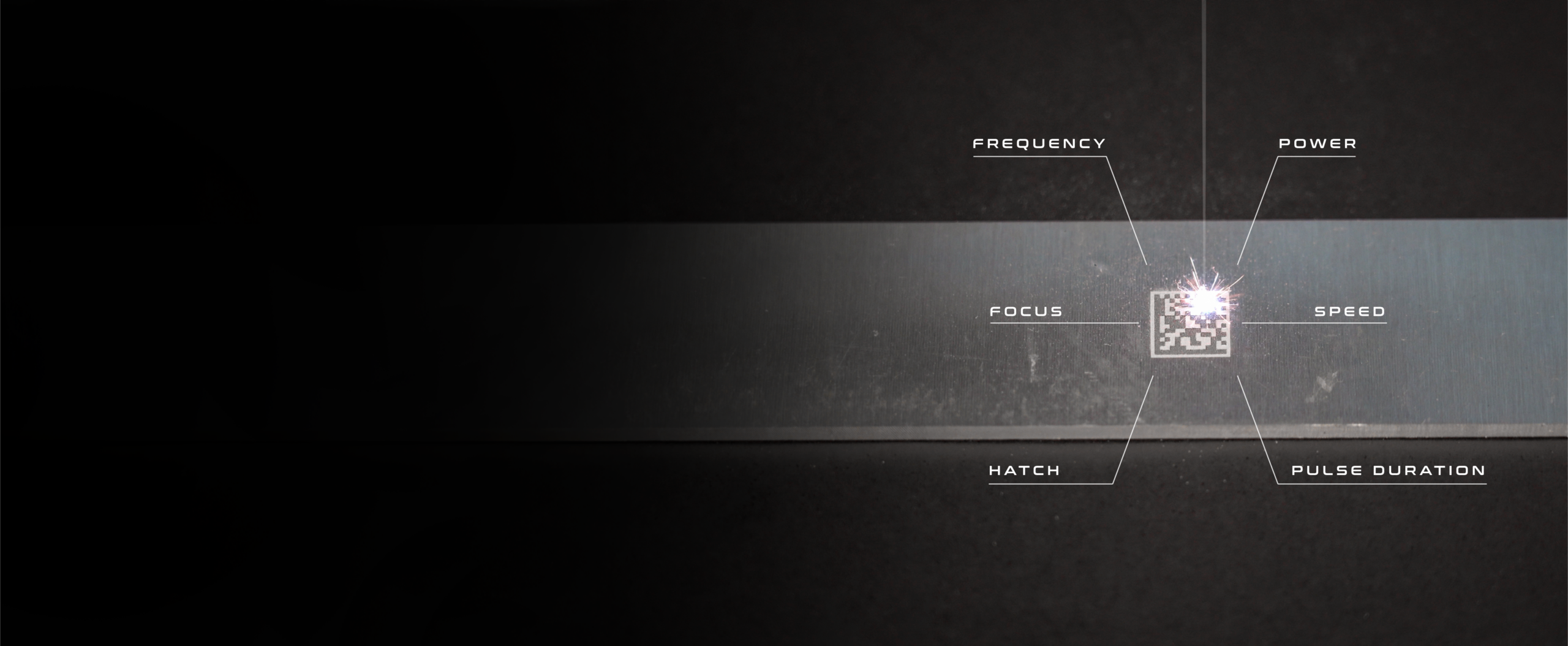
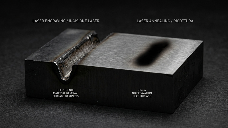
- Marking parameters and technique: power, speed, frequency, hatch spacing and number of passes, together with the chosen technique (such as annealing, engraving or coating removal), determine the shape, edges and uniformity of the module. With very small modules, even minor positioning or focusing deviations have a greater relative impact.
- Material and surface: composition, finish, roughness, reflectivity and surface treatments affect the material’s response to the laser. On a rough or machined surface, the material texture may be comparable in size to a very small module and interfere with readability.
- Contrast: the code is readable when the reader can reliably distinguish marked modules from unmarked ones. Contrast results from the combination of technique, parameters and material, but also depends on the lighting conditions under which the code is read.
For further information, read -> Laser Marking Parameters: How to Set and Optimise Them for Repeatable Results
The Reading System: Markable Does Not Mean Readable
The final link in the chain is the device that will read the code, and it is often what determines the actual limit. A reader or camera captures an image with a certain number of pixels distributed across the field of view: to decode the code reliably, each module must be covered by a sufficient number of pixels.
This ratio, known as pixels per module (PPM), depends on the sensor resolution, optics, reading distance and field of view; minimum values vary depending on the reader and decoding algorithms and must be verified against the specifications of the selected system.
The key point is therefore this: a very small module may be physically markable but not reliably readable by the intended system. The limitations of marking (spot size, optics, process and material) and those of reading (reader resolution, optics, lighting and distance) must therefore be considered together, and the module size must comply with both sets of requirements.
Moreover, there is not necessarily just one reader: the same code may need to be read by a fixed camera on the production line, a handheld scanner in a warehouse or a service technician years later. The correct reference is the most demanding reader throughout the component’s lifecycle, not the smallest detail that the laser source is capable of producing.
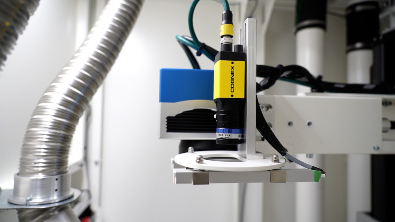
For further information, read -> Industrial Vision Systems for Precision Laser Applications
Marking, Reading and Verification: Three Distinct Operations
In traceability projects, terms referring to different operations are often used interchangeably. Keeping them separate helps define responsibilities and controls:
- Marking: the physical creation of the code on the component. The result depends on the source, parameters, material and positioning.
- Reading: the decoding of the code by a reader or vision system, through which the data is captured and recorded. A successful reading indicates that the specific reader, under those conditions, decoded the code, but does not indicate the available quality margin.
- Verification: the measurement of symbol quality according to standardised parameters and methods, using equipment and defined lighting conditions. It determines whether the code has sufficient margin to be read reliably by other readers, at other points in the supply chain and over time.

A code at the limit of readability may be successfully decoded by the production line reader but cause problems further down the line, with another device or after the surface has undergone wear or treatment.
For this reason, where traceability is critical, verification is carried out alongside reading, either on a sampling basis or directly on the production line, according to customer or industry requirements.
DPM Code Verification: Reference Standards
The quality of printed 2D codes is evaluated according to ISO/IEC 15415:2024, already mentioned in the section dedicated to DataMatrix. Codes marked directly on the component, however, present different conditions from those printed on labels: reflective metal surfaces, often lower contrast, and modules that may consist of dots rather than fully filled squares.
For these applications, the reference standard is ISO/IEC 29158:2025 (Bar code symbol quality test specification, Direct part mark), which replaced the 2020 edition. It adapts the methodology of ISO/IEC 15415 to DPM codes by introducing alternative lighting conditions and modifications to the measurement and evaluation of certain parameters.
Which standard to apply and which quality level to require depends on customer and industry specifications: in the automotive and aerospace sectors, for example, industry or manufacturer-specific specifications with their own requirements are widely used. For traceability, the key point is that code quality can be measured and documented, and can therefore become part of the process control system.
Evlaser Solutions
Industrial Laser MarkersLaser Marking Applications in Traceability
Medical Devices
For medical devices, laser marking is one of the most widely used technologies for the direct application of UDI codes, both for the quality of the marking and the permanence of the mark.
On metal or plastic instruments, laser marking does not require inks or additional materials and, with techniques and parameters suited to the material, can maintain readability throughout the required cleaning and sterilisation cycles.
On stainless steel, for example, annealing is often used, as it does not remove material. Laser technology also makes it possible to mark very small DataMatrix codes, subject to the available surface area, material and intended reading system.
Automotive: Permanent Identification of Components and Serial Numbers
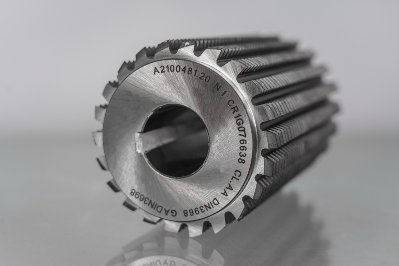
Another important application of laser technology is the automotive sector, where laser marking is used to clearly identify the various components that make up a vehicle with 2D codes, DataMatrix codes, serial numbers, the vehicle-related chassis identifier VIN (Vehicle Identification Number), and more.
Over recent decades, safety and reliability have become key priorities for vehicles, driving the automotive industry to continuously improve its traceability methods. In this context, the use of laser marking has progressively expanded.

Traceability operates here at multiple levels: the VIN identifies the vehicle throughout its lifetime, while part numbers, batch codes and serial numbers identify individual components, such as engine and transmission components, brake and steering parts, and electronic assemblies.
The code, often a DataMatrix combined with human-readable text, links each component to its production data, test results and the vehicle on which it is installed, and provides the basis for spare parts management and any recall campaigns.
Historically, permanent identification of metal components has mainly relied on mechanical techniques such as stamping and dot peen marking.
In many applications, laser marking is now a technological alternative, particularly where compact 2D codes, variable content from one component to another, cycle times compatible with automated production lines and the absence of mechanical stress on the component are required.
Mechanical techniques, however, remain the required or preferred choice in other cases. For the VIN, for example, Commission Implementing Regulation (EU) 2021/535 (Annex II) requires the marking to be applied to the chassis or an equivalent structure by stamping or mechanical hammering, allowing other techniques only if they demonstrate the same level of resistance to tampering and counterfeiting.
The choice between laser and mechanical techniques must therefore be made on a case-by-case basis, taking into account the material, the stage of the production cycle, regulatory and customer requirements, and the intended reading system.
For further information, read -> Traceability and Performance: EVLASER Innovation in Laser Marking of Brake Discs
Other Applications: Food Supply Chains and Anti-Counterfeiting
The same principles apply in other contexts. In the food supply chain, identification accompanies the product through every stage from producer to consumer: in the case of meat, for example, it starts with the ear tags of livestock and continues through the packaging.
In several industries, laser marking is also used as an anti-counterfeiting measure. A unique and permanent identifier linked to a database makes it more difficult to place unauthorised copies on the market and makes it possible to verify the origin of a component, because every valid code must correspond to data recorded by the manufacturer.
The Benefits of Laser Marking for Traceability
In summary, laser marking offers several benefits for industrial traceability, which should always be evaluated in relation to the material and application:
- Durability: the code is created directly in or on the surface of the material, without labels or inks that can detach or degrade. With the appropriate technique and parameters, it can withstand the wear, treatments and environments expected for the component; actual resistance must be verified under real operating conditions.
- Precision: the focused beam makes it possible to create fine details and compact codes with good repeatability from one component to another. The minimum usable size depends on the combination of optics, parameters, material and reading system.
- Integration and automation: laser marking can be integrated into automated production lines and manufacturing software systems, which generate the data to be marked, associate it with the component and record its history. The link between the code and the database also makes counterfeiting more difficult.
- Speed and operating costs: the process is fast and does not require consumables such as inks or labels. As with any industrial system, routine maintenance must nevertheless be taken into account and, depending on the material, fume extraction may be required.
- Non-contact process: marking does not exert mechanical stress on the component; the effect on the surface must be evaluated according to the material and the technique selected.