3D Laser Marking: how a scanning head with dynamic focus shifting works
When discussing 3D laser marking in an industrial context, the term refers to a specific technology: the ability to shift the focal point of the laser beam along the Z axis through an integrated optical system, without the scanning head moving physically.
This distinction is essential because it clearly separates the concept from volumetric engraving or the progressive removal of material, which are entirely different machining processes.
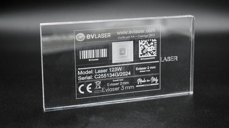
3D laser marking is therefore a solution for applying marks, codes, logos or traceability information to geometrically complex surfaces, while maintaining the quality and definition expected from a high-precision laser process.
In production processes where components feature curved, inclined or stepped surfaces, a conventional scanning head quickly reaches its limits. 3D laser marking technology was developed to overcome these limitations efficiently and effectively, without compromising the speed and repeatability typical of galvanometer-based systems.
What is 3D Laser Marking and How Does It Work?
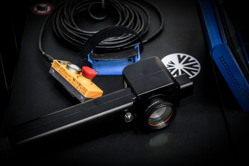
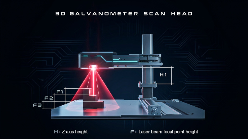
The operating principle of a 3D scanning head is based on the addition of an optical element, typically positioned before the pair of galvanometer mirrors, which makes it possible to shift the focal point along the Z axis in a controlled and programmable manner.
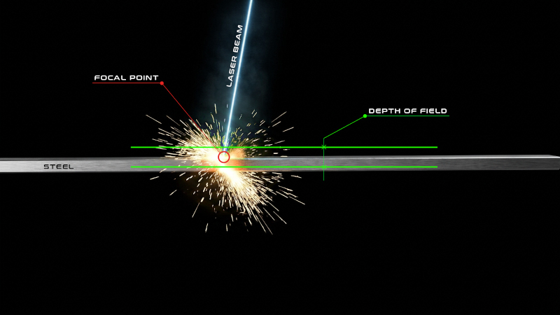
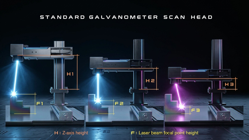
In a conventional system, the focal point is fixed at the nominal working distance defined by the f-theta lens; any variation in the height of the workpiece results in a loss of focus, directly affecting the quality of the marking. With a 3D scanning head, on the other hand, the software controls the focal shift in real time to follow the surface profile, maintaining the optimal energy density at every point.
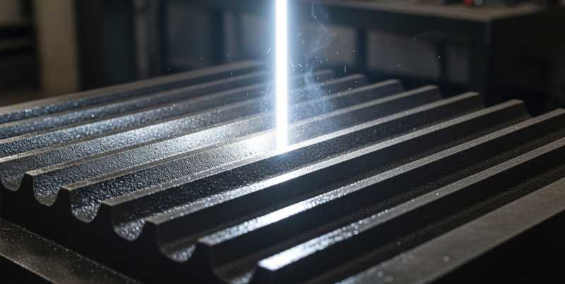
To better illustrate this concept, consider marking a logo on a hemisphere. If the laser is focused at the top of the dome, a conventional scanning head will produce acceptable marking only in the central area, while towards the edges the beam becomes defocused, the mark grows wider and shallower, and the image appears distorted. A 3D scanning head, by dynamically adjusting the focal point and applying geometric correction algorithms, compensates for distortions caused by the curvature of the part and ensures uniform marking across the entire surface.


However, it should be clearly stated that a 3D scanning head is not the optimal solution for every application. On perfectly flat parts with minimal flatness tolerances, a traditional 2D scanning head delivers equivalent or even superior performance at a lower cost.
Investing in a 3D laser marking system is fully justified when the component geometry varies along the Z axis, when pallets containing parts with different heights must be marked without repositioning the scanning head, or when productivity requires eliminating mechanical movement along the vertical axis.
Laser Sources Compatible with 3D Scanning Heads
A 3D scanning head is not tied to a specific laser technology: the principle of optical focal point shifting is compatible with different laser sources, provided that the optical system is correctly designed for the required wavelength and beam parameters.
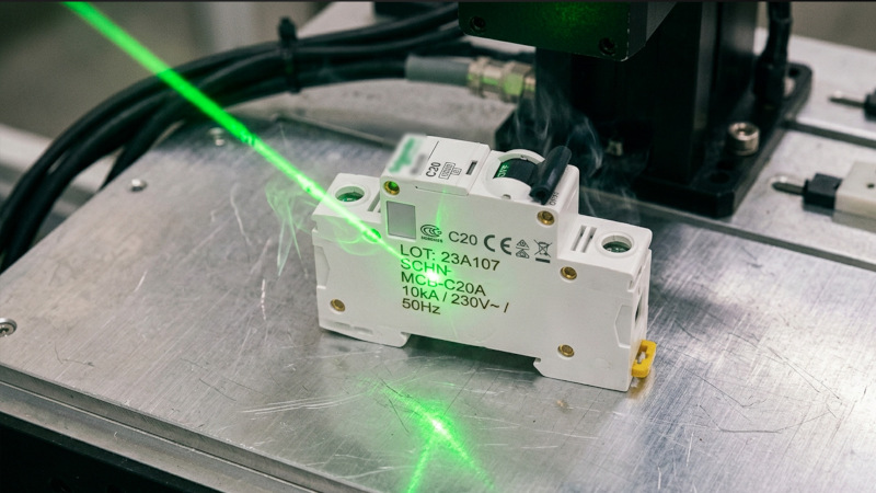
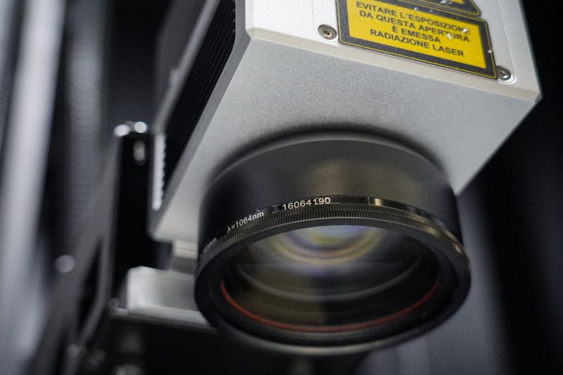
Fiber laser sources, among the most widely used in industrial applications for marking metals and plastics, can be easily integrated with 3D scanning heads, making them suitable for applications that require dynamic focal point control along the Z axis.
MOPA laser sources, a variant of fiber lasers that allows independent control of pulse duration and frequency, can also be integrated with 3D scanning heads when the application requires both advanced laser parameter control and the marking of surfaces with complex geometries.
CO₂ lasers, mainly used for non-metallic materials such as glass, ceramics, wood and polymers, can also be combined with 3D scanning heads, taking into account the optical considerations related to their far-infrared wavelength. UV lasers, used for low-heat applications on sensitive materials, benefit from the flexibility of a 3D scanning head when the surfaces to be marked are not flat.
In any case, the choice of laser source is determined primarily by the material and the type of marking required; the 3D scanning head acts as part of the optical scanning system, adding Z-axis control to beam management without changing the nature of the laser-material interaction.
Operational Challenges in 3D Laser Marking
Like any technology, 3D laser marking has its limitations and operational challenges, which must be understood to properly design the process and achieve reliable results.
The first factor to consider is the maximum available Z-axis travel. Optical focal point shifting still has a limited range. The focal point can typically be moved up to 40 mm above and 40 mm below the focal plane, providing a total travel of approximately 80 mm. Components with greater height variations than this range cannot be marked using the 3D scanning head alone and require additional mechanical movement of either the scanning head or the worktable.

The second limitation concerns the beam angle of incidence. As the focal point moves towards the limits of the Z-axis travel, the angle at which the laser beam strikes the surface increases. This has two consequences: the beam cross-section on the material becomes elliptical rather than circular, reducing the energy density, and the marking may exhibit slight geometric distortion.
Correction software integrated into modern 3D scanning heads can partially compensate for this effect, but process design must still take the actual geometry of the workpiece into account in order to define the optimal parameters for each area.
The final marking quality therefore depends not only on the scanning head technology itself, but also on the proper engineering of the process: accurate mapping of the component’s Z profile, definition of the working areas, and optimization of laser parameters for each height level. Inadequate process design can negate the advantages of a 3D scanning head, resulting in non-uniform marking even on geometries that are theoretically within its capabilities.
Industrial and Custom Solutions
Laser MarkingTechnical Advantages of 3D Laser Marking
The benefits of a 3D scanning head are best understood when considered in the context of the overall production process, rather than as isolated technical features.
The most immediate advantage is the elimination of mechanical movement along the Z axis. In a conventional system, marking components at different heights requires physically moving either the scanning head or the worktable between operations, increasing cycle times and reducing productivity.
With a 3D scanning head, height changes are performed optically in just a few milliseconds, eliminating mechanical inertia and wear on moving components.

The main technical advantages that translate into practical operational benefits include the following:
- Marking mixed pallets: different components with varying heights can be processed in a single operation without stopping the machine to reposition the scanning head. This is particularly beneficial in assembly lines with frequent product variations.
- Reduced processing cycles: eliminating mechanical Z-axis movement directly results in shorter cycle times and higher hourly production capacity.
- Consistent quality on complex surfaces: dynamic focus adjustment and distortion correction algorithms ensure sharp, readable markings on geometries that would be challenging for a conventional system.
- Multi-level marking preview: software used with 3D scanning heads allows simulated marking to be displayed across different height levels of the component, making it easier to verify the process before production.
- Reduced need for dedicated fixtures: in some applications, the flexibility of the 3D scanning head reduces the number of fixtures or supports required to position components at precise heights, lowering tooling costs.
Typical Applications and Target Industries
3D laser marking is primarily used in industries where the geometric complexity of components is the rule rather than the exception.
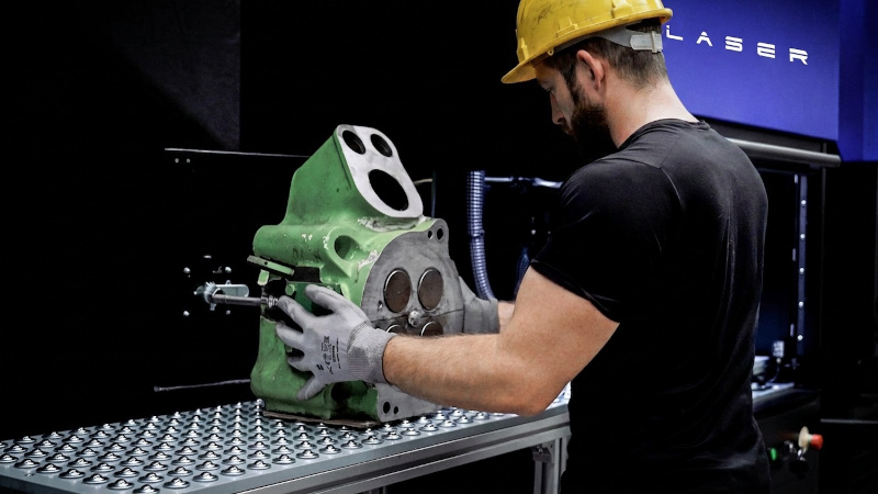
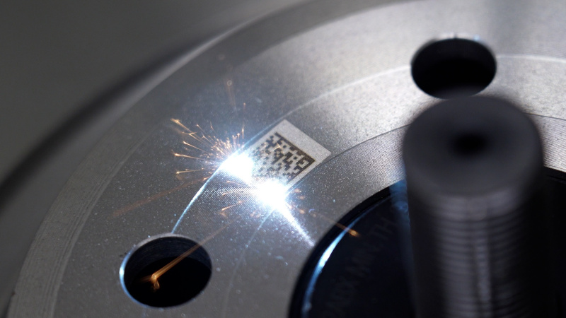
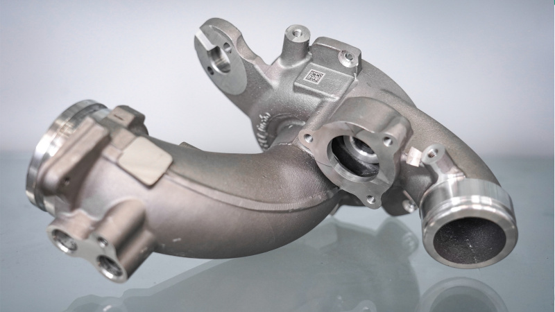
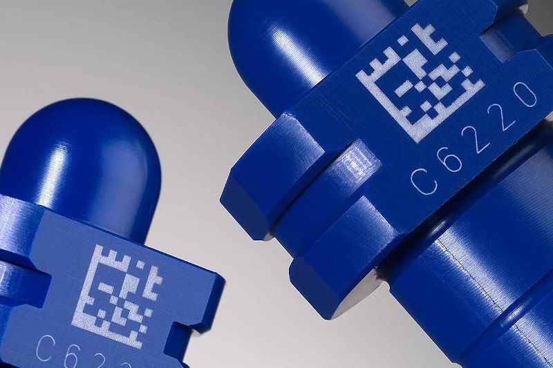
In the automotive industry, pistons, cylinder heads, transmission components and hydraulic fittings often feature curved surfaces and varying heights, making them difficult to mark using conventional systems. The traceability of these components, required for both quality assurance and regulatory compliance, must be ensured through durable and readable codes. A 3D scanning head makes it possible to apply Data Matrix and alphanumeric codes to non-flat surfaces without compromising readability.
In the medical industry, surgical instruments, implants and medical devices feature three-dimensional geometries that require permanent markings for UDI (Unique Device Identification) traceability under the European Medical Device Regulation (MDR 2017/745). The ability to mark cylindrical and spherical surfaces with high precision, without affecting adjacent areas of the material, is a requirement effectively met by the 3D scanning head.
In the aerospace and defense sectors, structural components and turbine engine parts require durable identification markings capable of withstanding extreme temperatures and mechanical stress, often on complex geometries. The precision and repeatability of 3D laser marking meet the demanding quality standards of these industries.
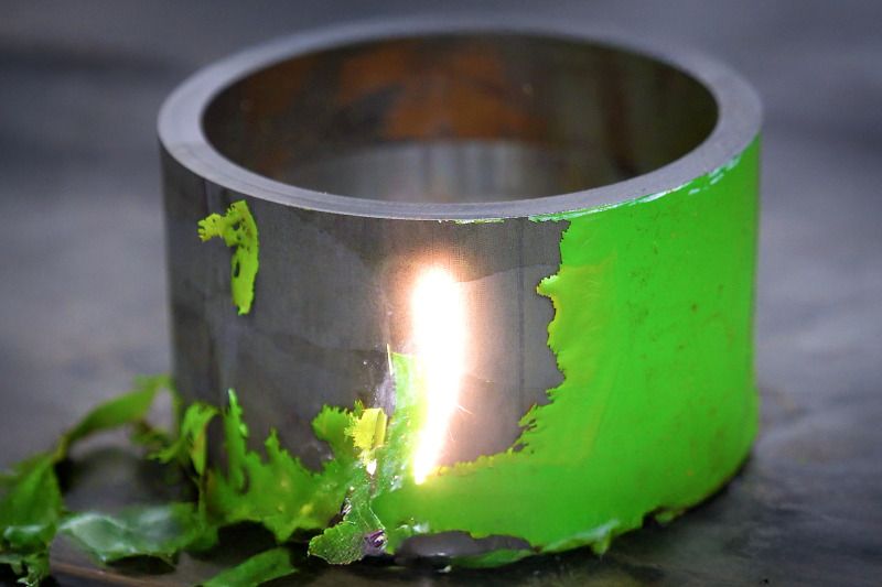
The industrial valve and fluid handling industry also benefits from 3D laser marking. Valve bodies with irregular geometries, flanges and fittings with inclined surfaces can be permanently marked with highly readable markings suitable for automatic inspection systems.
3D Laser Marking as a Process Choice
3D laser marking with dynamic focal point shifting along the Z axis provides a mature technical solution to a common challenge in modern manufacturing: how to achieve high-quality marking on geometrically complex components without compromising productivity or flexibility.
It is not a universal technology, and its implementation requires a careful analysis of part geometry, height variations and marking requirements.
When these conditions are met, however, integrating a 3D scanning head into an industrial laser system transforms the marking of curved, cylindrical or multi-level surfaces into a reliable, repeatable and efficient production process, bringing the quality of marking on complex geometries close to that achieved on flat surfaces.