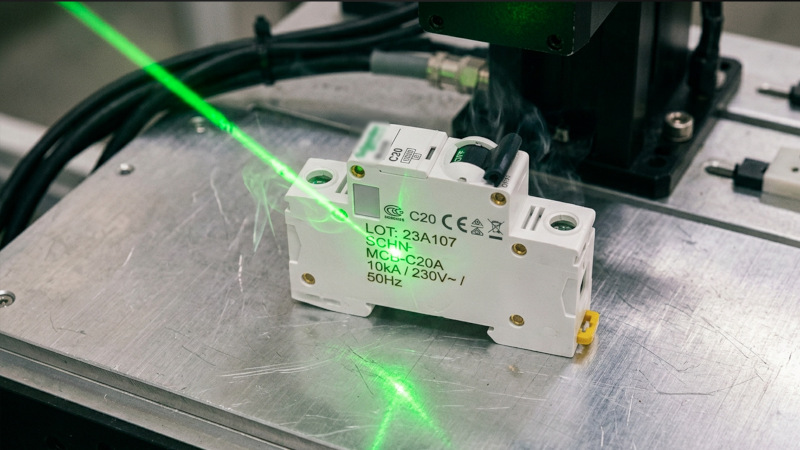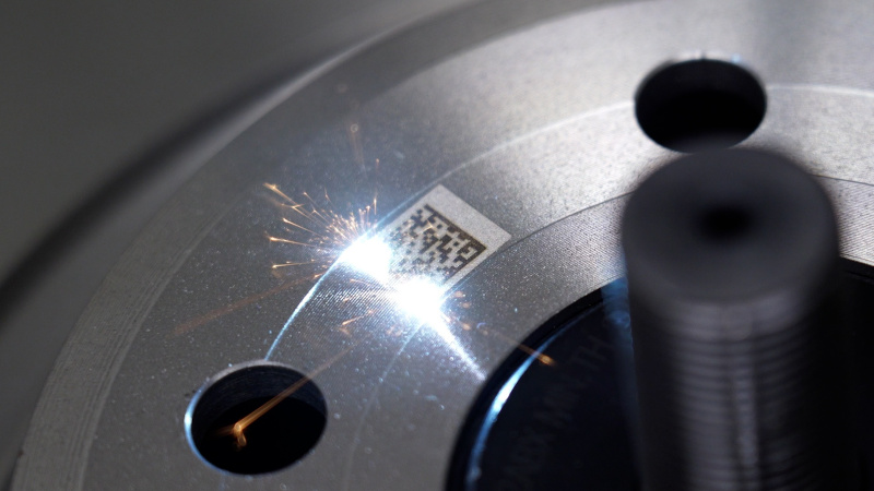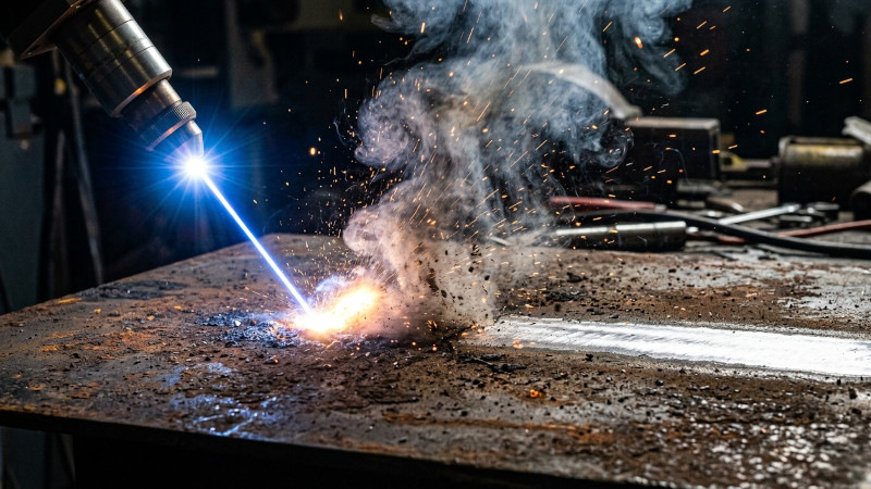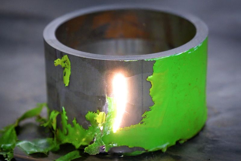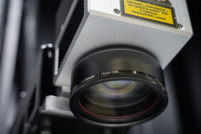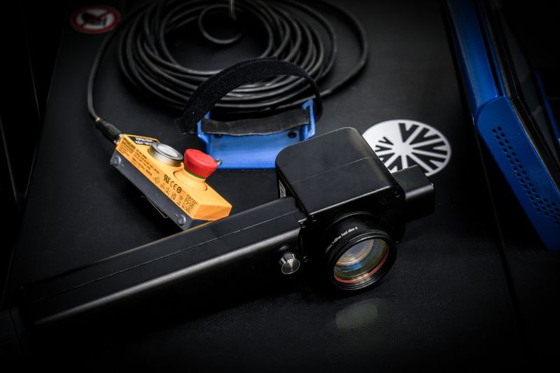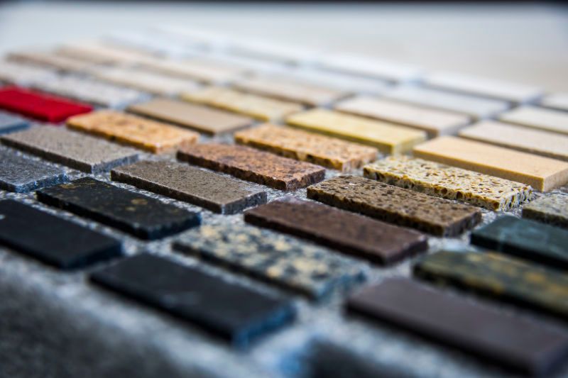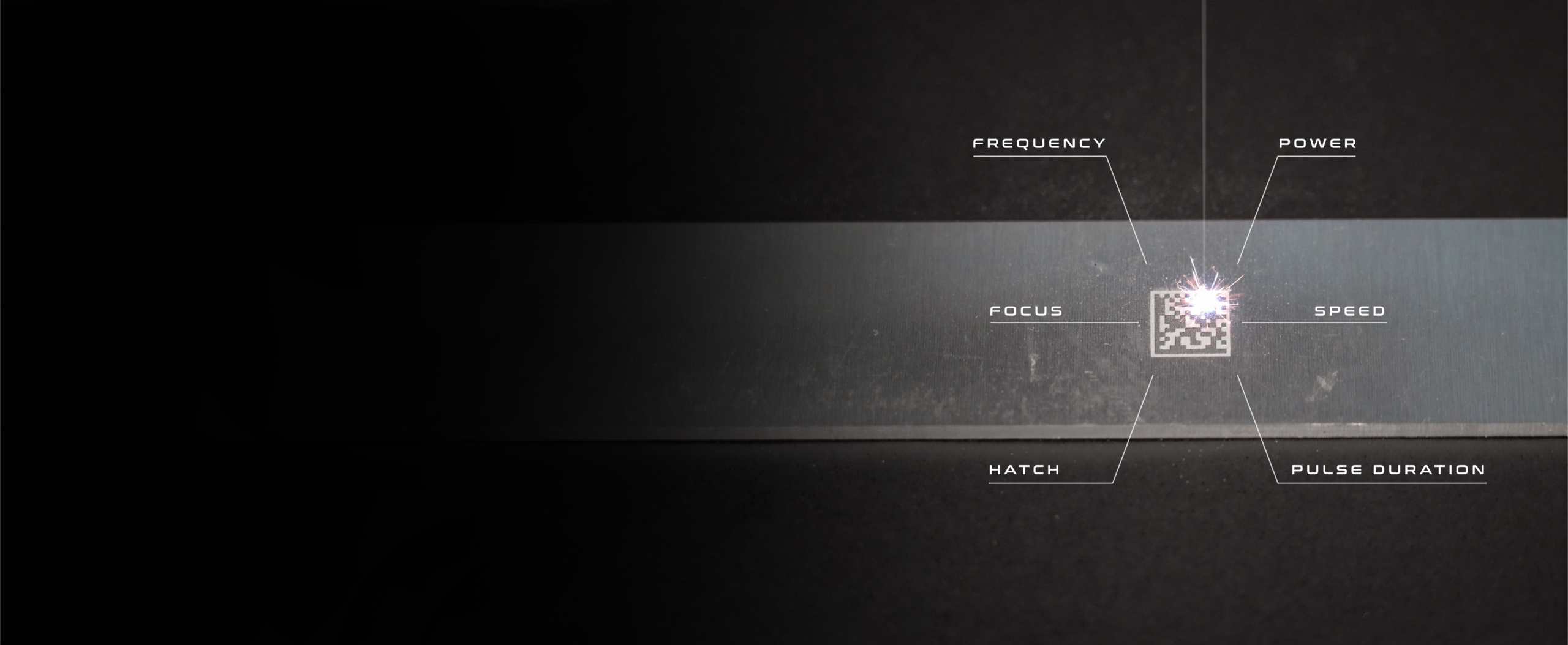
The result of laser marking never depends on a single value set on the machine, but on the balance between multiple variables acting together on the material. Adjusting laser marking parameters means simultaneously managing the energy transferred by the beam, its distribution over time and space, and the optical and geometric characteristics that determine how it is applied to the surface.
Understanding the role of each laser parameter, and above all how it interacts with the others, is essential to achieving clear, uniform and repeatable markings over time, regardless of the material being processed or the application sector.
What are Laser Marking Parameters
When discussing laser parameters, it is useful to distinguish between three groups of variables which, although different in nature, all contribute to the final result: laser and process parameters, the optical parameter related to focusing, and design parameters, which determine how the beam is guided across the surface.
None of these categories can be optimised in isolation: changing one will almost always affect the others.
The most relevant laser and process parameters include the following.
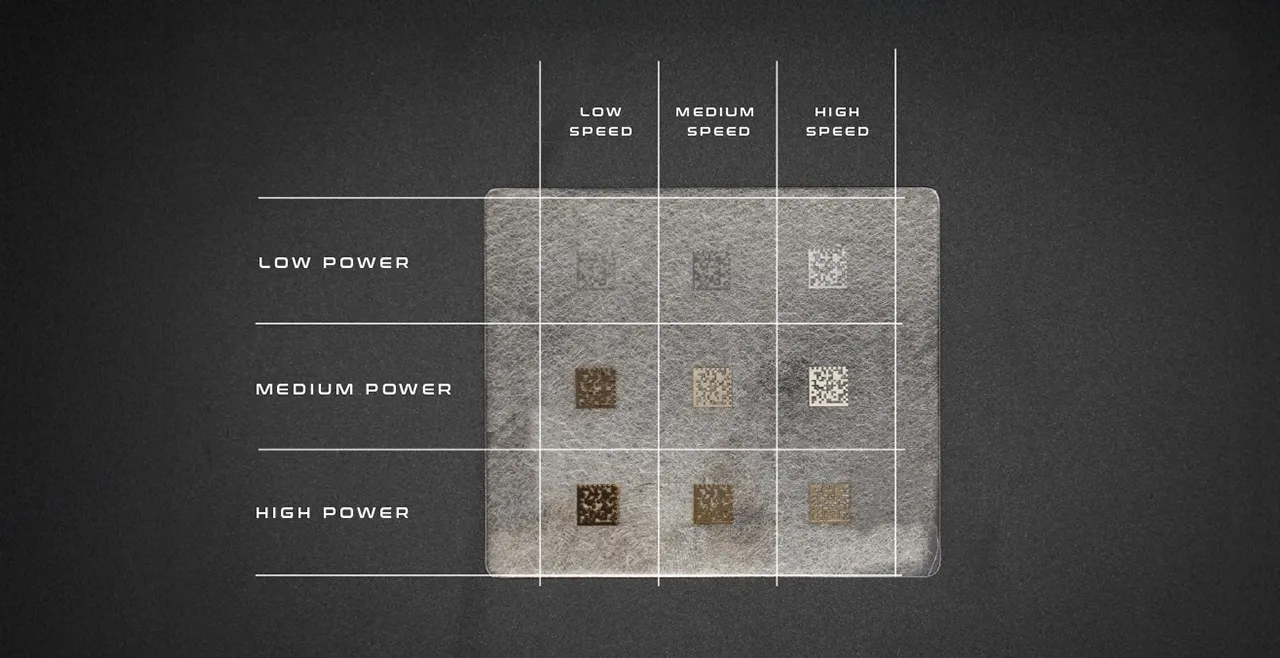
- Power: expressed in watts, it is the average amount of energy delivered by the source per unit of time. Higher power does not automatically result in deeper or more visible marking, as the actual effect depends on how that energy is distributed over time and concentrated in space; power also affects the achievable processing speed.
- Scanning speed: this is the speed at which the beam moves across the surface and determines the dwell time at each point, and therefore the actual linear energy deposited; lower speeds increase the energy input per unit of length, while higher speeds reduce it.
- Pulse repetition frequency: in pulsed systems, this defines how many pulses are emitted per second and is measured in kHz. Depending on the average power and the characteristics of the source, changing the frequency also affects the energy associated with individual pulses and their distribution over time.
- Pulse duration: this is the time over which the energy of a single pulse is released, typically in the nanosecond range or, in more advanced systems, in the picosecond range. Shorter pulses concentrate energy over extremely short periods, limiting heat diffusion to the surrounding areas; longer pulses promote more gradual thermal effects, which can be useful, for example, for annealing.
- Number of passes: indicates how many times the beam retraces the same path. Increasing the number of passes makes it possible to build up energy progressively, but the result is never a simple linear sum of the effects of a single pass, because the condition of the material changes after each pass.
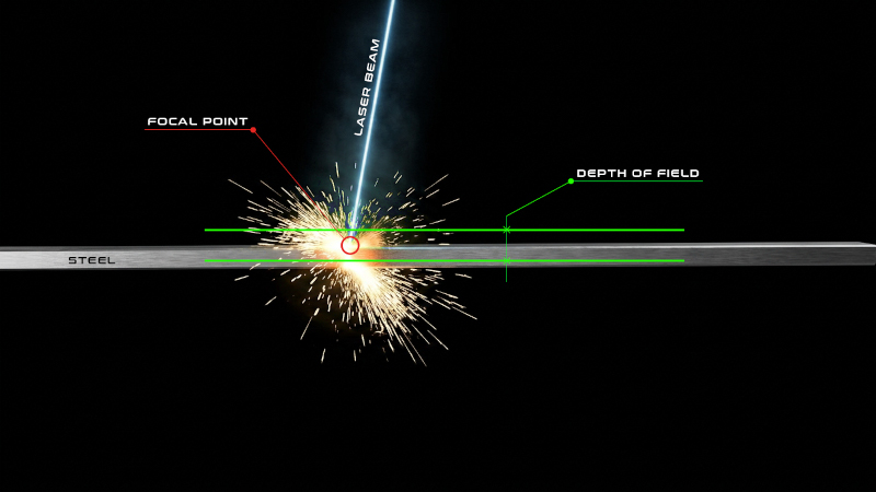
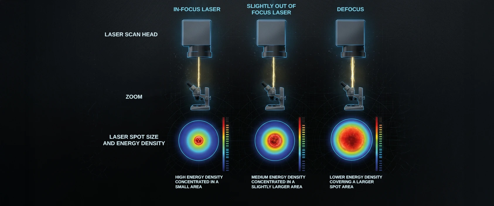
Focusing, or defocusing, on the other hand, is an optical parameter: it defines the position of the working plane in relation to the point at which the beam reaches its minimum diameter and therefore its maximum energy density per unit area.
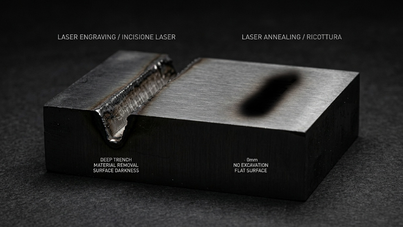
Working exactly at focus concentrates the energy into the smallest possible spot, a condition that favours sharp and deep engraving; moving away from the focal plane in a controlled manner increases the spot size and reduces energy density, an effect deliberately sought in certain annealing or surface marking applications.
The difference between these conditions is not merely theoretical, but results in concrete and clearly distinguishable effects on the material, depending on how the same energy is distributed over a different surface area.
- In focus: the beam is concentrated into the minimum spot diameter allowed by the optics, resulting in maximum energy density per unit area. This condition offers the greatest material removal and penetration capability, making it suitable for deep engraving and high-contrast marking on materials that require energy to be concentrated within a small area.
- Slightly out of focus: by moving the working plane slightly away from the point of minimum diameter, the spot expands moderately and the same energy is distributed over a slightly larger surface area. Energy density decreases without dropping dramatically, providing a compromise often sought when the aim is to reduce the material removal effect while maintaining a clear mark, or when working on surfaces that are not perfectly flat.
- Significant defocus: by moving the workpiece further away from the focal plane, the spot expands considerably and energy density decreases accordingly, favouring a more superficial and diffuse thermal effect rather than material removal. This is the condition typically sought for annealing or marking applications where the surface must remain relatively unaffected, as the objective is not to remove material but to induce a controlled transformation of the outermost layer.
In all three cases, the parameter that actually changes is not the power setting, but the surface area over which that power is distributed: this relationship, rather than the individual defocus value, determines whether the result will be deep engraving, a balanced mark or a purely thermal effect.
Hatching and hatch angle fall within the category of design parameters: they describe how the beam fills a solid area by tracing parallel lines according to a specific orientation.
Hatching also involves the distance between fill lines, known as hatch distance: a distance that is too wide leaves portions of the surface untreated or uneven, while a distance that is too narrow results in excessive overlap between the lines, increasing the total amount of energy deposited over the area.
The hatch angle, meaning the orientation of the fill lines in relation to the outline of the shape, also affects the visual uniformity of the result, particularly on large surfaces or complex geometries.
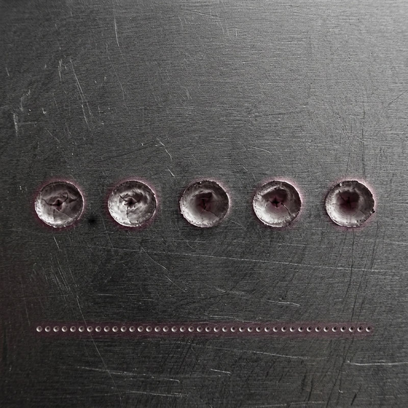
Hatch distance in laser marking with different hatching configurations
Laser marking with a narrow hatch distance and closely spaced fill lines
Effects of fill line overlap in laser marking
These parameters are also linked by the relationship between frequency and speed, known as pulse overlap: the overlap between one pulse and the next, determined by the ratio between speed and frequency, affects the continuity of the mark.
Insufficient overlap produces dotted or discontinuous markings, while excessive overlap concentrates too much energy within a limited surface area.
How to configure and optimise Laser Marking Parameters
Setting the parameters for laser marking does not follow a one-size-fits-all formula, but rather a methodical process that starts with the material and the expected result: high-contrast marking, deep engraving, an annealing effect or selective layer removal require different approaches, starting with the choice of laser source.
A practical approach that many technicians follow during the setup phase can be described through the following steps, intended as a working framework rather than a rigid sequence.
- Identifying the material and its absorption characteristics.
- Clearly defining the desired result in terms of contrast, depth or visual effect.
- Selecting the laser source best suited to the material and the intended outcome.
- Identifying an initial power range, generally based on the technical documentation provided by the laser source manufacturer.
- Testing different scanning speeds within that range and observing their effect on contrast and depth.
- Adjusting frequency and pulse duration to fine-tune the balance between thermal effects and material removal.
- Evaluating the results in terms of contrast, depth and visual quality of the mark.
- Selecting the combination of parameters that best meets the requirements, while also taking processing time into account.
- Verifying repeatability of the selected combination across multiple samples, an essential condition before transferring the process to production.
This process varies depending on the laser source used, as each technology interacts differently with the same material.
Fiber lasers, with wavelengths in the near-infrared range, are widely used for metal marking. Fibre sources with MOPA architecture offer greater flexibility in controlling pulse duration and therefore in managing the interaction with the material.
CO2 lasers, with their much longer wavelength, are preferentially used on organic and non-metallic materials such as wood, plastics, leather and paper.
UV lasers, thanks to their shorter wavelength, can promote interactions with reduced thermal input compared with other sources in certain applications, making them particularly interesting for heat-sensitive materials.
|
PARAMETER |
If Increased |
Possible Effect |
|
Power |
> |
More energy delivered to the workpiece |
|
Speed |
> |
Less energy per unit area |
|
Frequency |
> |
Higher pulse density |
|
Number of passes |
> |
Greater depth/overall energy input |
|
Hatch |
> |
Less overlap between fill lines |
|
Defocus |
> |
Larger spot, lower energy density |
|
Pulse duration |
> |
Greater thermal component, with all other conditions remaining unchanged |
A further element of the configuration is the choice of focusing optics.
The lens determines the working area covered by the system, the minimum achievable spot size and, consequently, the resolution of the mark and the energy density available at that point; lenses with shorter focal lengths concentrate energy within smaller working areas, with smaller spots and higher energy density, while lenses with longer focal lengths cover larger areas with lower energy density at the same power.
The topic would deserve a dedicated in-depth analysis: here, it is sufficient to remember that the choice of lens is a configuration variable to be considered alongside power, speed and frequency.
How do the Parameters interact
No laser marking parameter acts in isolation: changing one will almost always alter the effect produced by the others, and it is this network of interrelated factors that makes laser marking a process to be fine-tuned through successive tests rather than calculated in the abstract.
The most direct relationship is that between frequency and speed, which determines the pulse overlap described above: increasing the speed without changing the frequency reduces the overlap between consecutive pulses, while increasing the frequency at the same speed increases it.
A second close relationship exists between power and pulse duration, which together determine the energy effectively contained in each pulse: at the same average power, shorter pulses concentrate the same energy over a shorter period of time, increasing the peak power and therefore the material removal effect.
The number of passes is also directly related to the hatch distance: a combination of multiple passes with a narrow hatch distance produces a different energy build-up, in terms of spatial distribution, compared with a single pass using the same distance.
Finally, focusing interacts directly with spot size and therefore with the available energy density: the same combination of power, speed and frequency can produce very different results depending on whether the workpiece is positioned exactly on the focal plane or slightly out of focus.
Precisely because of this interdependence, the material being processed, the laser source used, the selected optics and the desired result all influence the most suitable combination of parameters: there is no universally valid configuration, only combinations empirically verified for a specific application.
Benefits of correctly setting Laser Marking Parameters and common issues
A correct configuration of laser marking parameters delivers measurable benefits: greater mark uniformity across the entire processed surface, consistent contrast from one workpiece to another, geometric accuracy of the reproduced design and, last but not least, process repeatability over time, an essential requirement wherever marking must remain compliant from batch to batch.
Conversely, some recurring mistakes can compromise the quality of the result, often because they stem from an approach that considers parameters individually rather than as a whole.
- Simply increasing the power to obtain a more visible mark: the depth and intensity of the mark depend on the combination of multiple factors, not on the power delivered alone; an uncontrolled increase can generate excessive heat and damage the material instead of improving readability.
- Excessively reducing the speed to compensate for an insufficiently visible mark: this increases the beam dwell time at each point, raising the linear energy deposited well beyond what is necessary, with the risk of burning or deforming the material.
- Using the same parameters on different materials: each material has its own absorption characteristics and heat sensitivity, so a combination optimised for one metal can rarely be transferred without modification to a plastic or organic material.
- Ignoring correct focusing: working away from the focal plane, even by just a few millimetres, alters the available energy density and therefore the quality and depth of the marking, often in ways that cannot be predicted without empirical testing.
- Not considering the number of passes and its relationship with hatch distance: setting multiple passes without reassessing the hatch distance can produce non-uniform energy build-up, with some areas overexposed and others insufficiently processed.
Each configuration must therefore be validated on the specific material and application, avoiding the assumption that a single setting can serve as a universal solution.
Discover Evlaser Solutions
Industrial Laser MarkersTypical applications and industries
The selection and configuration of laser marking parameters vary significantly depending on the application sector and the result required by the production process.
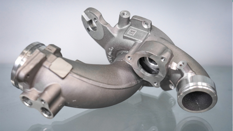
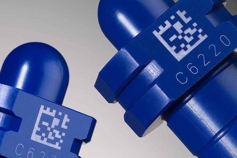
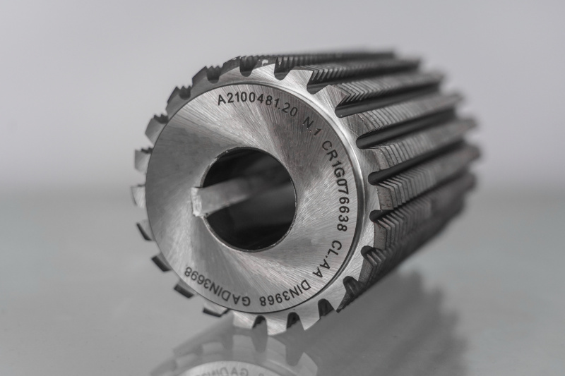
In mechanical components and the automotive industry, where traceability is often a regulatory requirement, priority is generally given to high-contrast markings and reliably readable barcodes or data matrix codes, even after subsequent surface treatments such as painting or galvanic treatments. Here, the combination of parameters must ensure a mark that remains stable over time and resistant to abrasion and corrosion.
In the medical sector, marking surgical instruments and implantable devices requires parameters capable of producing legible marks without altering the surface properties of the material, often stainless steels or biocompatible alloys, where excessive thermal energy could compromise corrosion resistance.
In the electronics industry, where components are often heat-sensitive and geometries particularly small, the requirement is the opposite: parameters must minimise thermal impact, a condition in which UV lasers are often used because of their ability to interact through predominantly photochemical mechanisms.
In the packaging and consumer goods sector, where very different materials coexist, from plastics and glass to paper-based materials, parameter configuration must be redefined whenever the material being processed changes, precisely because the absorption of the wavelength used varies substantially from one material to another.
A balance to be built, not improvised
Setting laser marking parameters means managing an interdependent system of variables, in which power, speed, frequency, pulse duration and number of passes interact with focusing and the geometric characteristics of the design, such as hatching and hatch distance.
None of these elements, considered individually, can guarantee a high-quality result: it is their coordinated optimisation, calibrated according to the material, the laser source used and the selected optics, that determines markings that are uniform, legible and repeatable over time.
For this reason, rather than looking for universal values, it is preferable to develop a working method based on understanding the relationships between parameters and, through systematic testing, arriving at a validated and repeatable combination for each specific application.